





PCB Design Rules: What DRC Checks and Why It Matters
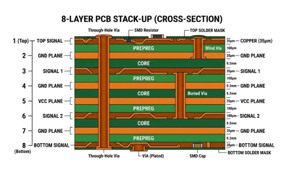
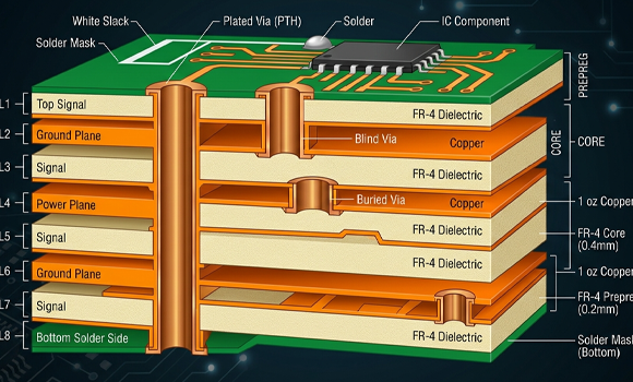
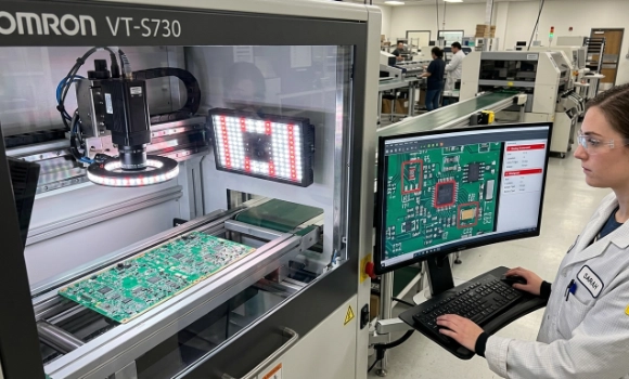

PCB design rules define layout constraints such as trace widths, copper clearances, hole sizes and board edge spacing. Design Rule Check, or DRC, compares a PCB layout against these configured limits to flag potential violations before fabrication. Setting rules that reflect electrical requirements and manufacturer capabilities helps identify issues early and reduce avoidable revisions. However, passing DRC does not confirm complete manufacturability or circuit performance. Designers should also review fabrication outputs, assembly requirements and any exceptions before releasing production files.
2. What DRC Actually Checks
DRC verifies both physical and electrical constraints, including:
- Minimum trace width
- Minimum spacing (clearance)
- Via and drill constraints
- Annular ring size
- Solder mask expansion
- Copper-to-edge distance
3. Types of Design Rules
3.1 Electrical Rules
- Net connectivity
- Short circuit prevention
- High-speed constraints
3.2 Manufacturing Rules
- Minimum drill size
- Copper thickness constraints
- Aspect ratio limitations
3.3 Assembly Rules
- Component spacing
- Solder mask alignment
- Via-in-pad constraints
4. DRC Workflow
- Schematic → Netlist generation
- PCB layout routing
- Rule definition (based on fab capability)
- Automated DRC execution
- Error review and correction
- Final validation before fabrication
5. DRC vs ERC
| Feature | DRC | ERC |
| Stage | PCB layout | Schematic |
| Focus | Geometry | Logic |
| Output | Manufacturing errors | Electrical logic errors |
6. Critical DRC Violations
- Trace spacing violations → short risk
- Via too small → fabrication failure
- Copper too close to edge → delamination risk
- Solder mask overlap issues → solder bridging
7. DRC in High-Speed PCB Design
In high-speed designs, DRC also enforces:
- Impedance-controlled routing
- Differential pair spacing
- Length matching constraints
8. Manufacturing Alignment (DFM Integration)
Modern PCB workflows combine:
- DRC (design-side validation)
- DFM (manufacturing feasibility check)
This ensures first-pass yield success.
9. Industry Standards
- IPC-2221 (generic PCB design rules)
- IPC-7351 (land pattern design)
- Manufacturer-specific DFM rules
Ready for Production? Kickstart Your Project Now. info@ysx-tech.com
Unsure About the Design? Consult with Our Lead Engineers Today. contact us


